MAY 30, 2024 BY AHARON ETENGOFF
Collected at : https://www.eeworldonline.com/how-to-select-an-iot-device-antenna/
When designing wireless connectivity into IoT devices, you have several options for antennas. You can design one right into a PCB, but several commercial options take the work out of designing your own.
Impacting range and performance, antenna selection, and placement are key design considerations for Internet of Things (IoT) device manufacturers. This article reviews the most widely used IoT antennas and discusses their application-specific functions. It also highlights optimal design and placement strategies, offering detailed guidelines for each antenna type.
Range and frequency requirements
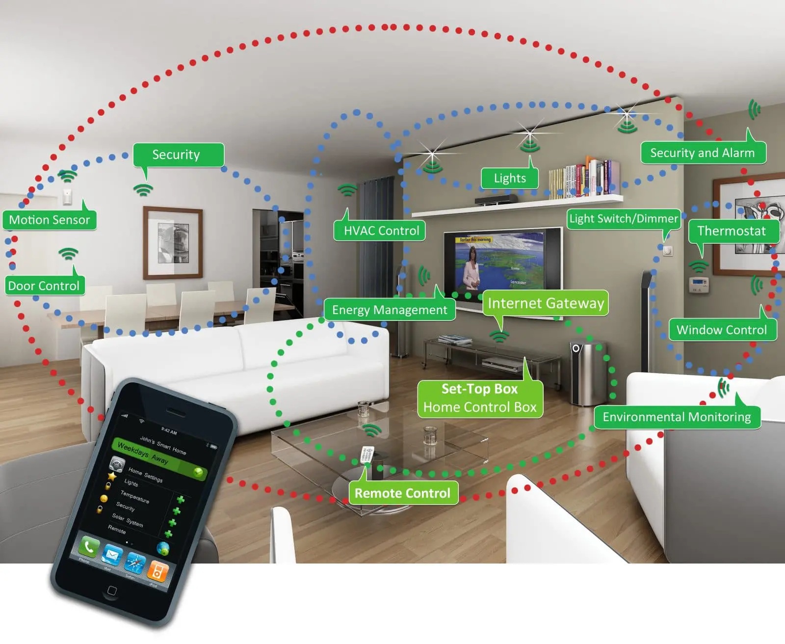
Figure 1. A Wi-Fi-enabled smart home setup highlighting interconnected devices for comprehensive home automation, encompassing lighting, climate, security, and energy management, all controlled from a central smartphone app. (Image: Bosch)
Range and frequency requirements play a crucial role in determining an IoT device’s antenna type. Wearables and smart home devices, for example, generally use Wi-Fi (Figure 1) or Bluetooth for short-distance communication across 2.4 GHz to 5.9 GHz. Operating in the same industrial, scientific, and medical (ISM) band, Zigbee supports smart home infrastructure and building automation with its efficient mesh networking capabilities.
In contrast, Industrial IoT (IIoT) applications typically rely on Low-Power Wide Area Network (LPWAN), which includes NarrowBand-Internet of Things (NB-IoT) and LoRaWAN communication protocols. NB-IoT provides broad coverage with licensed sub-1 GHz bands, while LoRaWAN achieves extensive reach using unlicensed sub-GHz frequencies (868 MHz in Europe and 915 MHz in North America).
Pairing high bandwidth and throughput with efficient power consumption, LTE Cat-M operates in licensed LTE bands below 1 GHz, facilitating seamless connections in challenging indoor locations.
High-speed, low-latency IoT applications use 5G’s wide spectrum, which spans sub-6 GHz and mmWave bands (24 GHz to 71 GHz), for broad coverage and high capacity. Notably, 5G is an increasingly popular choice for advanced automotive systems and healthcare devices, as well as virtual reality (VR) and augmented reality (AR) applications.
From whip and paddle to chip and wire
Selecting an IoT antenna involves navigating trade-offs between range, durability, cost, and integration complexity. Designed to meet specific application and frequency requirements, some of the most widely used IoT antennas include:
- Whip and paddle: Delivering wide-area connectivity for IIoT deployments, external whip and paddle antennas provide optimal performance and range for ISM, LoRa, LPWAN applications, as well as LTE Cat-M devices below 1 GHz. For durability and performance, whip and paddle antennas are manufactured with high-grade plastics and metals such as stainless steel or aluminum, incurring higher design costs compared to their rubber duck counterparts.
- Rubber duck: Featuring a helical design, external rubber duck antennas target portable IoT devices, handheld radios, and walkie-talkies. Offering a balance of durability, performance, and cost, rubber duck antennas are compatible with a broad frequency range, typically spanning 100 MHz to 2.5 GHz, including Zigbee’s 2.4 GHz band. These antennas are manufactured with flexible plastics and metals, such as stainless steel.
- Patch: Accommodating specific or dual polarizations for optimal satellite transmissions, patch antennas are a popular choice for GPS-enabled devices. Effective in the GHz range, particularly for GPS at 1.57542 GHz (L1 band), patch antennas ensure precise navigation with optimal gain and radiation characteristics.
- PCB: Offering design flexibility and higher gains for wearables and remote sensors, these integrated antennas accommodate a wide spectrum (including 5G), ranging from sub-6 GHz for extensive coverage to mmWave bands (24 GHz and above) for high-capacity applications. PCB antennas are manufactured using copper or other conductive metals deposited on a non-conductive substrate such as FR-4 fiberglass. Although adaptable for many different types of IoT applications and communication protocols, PCB antennas pose various integration challenges for systems designers, including signal interference and precise placement requirements.
- Chip: Accommodating small IoT devices, chip antennas efficiently support a diverse set of protocols and frequency bands, from Wi-Fi, Bluetooth, and Zigbee to LTE, NB-IoT, LoRa, and 5G. Because chip antennas demand a high level of integration, system designers must contend with space constraints on densely populated boards. Chip antennas are manufactured using conventional semiconductor materials, such as ceramic or silicon.
- Wire: Targeting connected cars, smart buildings, and other popular IoT applications, wire antennas are relatively inexpensive due to established manufacturing processes and readily available materials, such as copper or aluminum. Although wire antennas support multiple protocols, frequencies, and ranges, they pose various design challenges, including additional space for lower frequencies (which require larger antennas) and reducing or mitigating interference in dense layouts. Both design considerations are crucial for LTE Cat-M and 5G applications.
Optimizing range and performance with strategic design and placement
For whip, paddle, and rubber-duck antennas, ground plane considerations, including the conductivity of nearby surfaces, are crucial to maximize radiation efficiency. Optimizing this key parameter directly impacts signal strength and quality, ensuring stable and clear communication over longer distances. With a conducting plane of at least a quarter wavelength, these external antennas effectively mimic a dipole’s radiation pattern, significantly boosting range, particularly on the lower end of the ultra-high frequency (UHF) spectrum. Strategic placement, away from the device’s metallic components and edges, reduces interference and further maximizes range.
With sizes inversely related to frequency, wire antennas present unique design considerations that necessitate careful planning. For example, lower frequencies require larger antennas, potentially complicating small-scale IoT device integration. They also demand meticulous alignment, with a focus on defining the primary communication path and minimizing obstructions to ensure clear line-of-sight connections. Wire antennas must also remain separated from metallic elements such as housings, connectors, and device edges to maintain interference-free resonant frequency.
Patch antennas for IoT GPS devices require deliberate polarization selection (RHCP, LHCP, or both) to optimize satellite signal reception — with dual polarization achievable through PIN diodes or RF MEMS devices for transmission flexibility. Proper placement is key, as patch antennas must be mounted with a clear line of sight to the sky to minimize obstructions and bolster signal clarity, ensuring an unimpeded field of view (FOV). Although a flat profile streamlines integration on device surfaces, patch antennas must be positioned away from metal components to avoid interference and signal degradation.
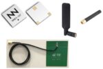
For compact IoT devices, choosing between PCB and chip antennas (Figure 3) depends on size constraints and performance requirements. PCB antennas, for example, are capable of higher gains due to their larger size and complex topologies (e.g., inverted-F, L, and folded monopole designs), yet may occupy significantly more board space.
Conversely, chip antennas offer a more compact solution with lower gains, fitting well in space-constrained applications such as wearables. Lastly, proper placement is crucial for both PCB and chip antennas. Specifically, minimal obstruction and strategic edge positioning boosts PCB antenna performance, while precise integration for chip antennas prevents component interference and maintains unobstructed signal paths.
For 5G-specific IoT devices, high-gain chip, wire, and PCB antennas can be leveraged as phased arrays. This configuration facilitates efficient spatial multiplexing and signal management, accommodating higher cell densities through widespread implementation of Multiple Input Multiple Output (MIMO) technologies. Additionally, adaptive beam-switching dynamically optimizes antenna signal paths, reducing potential interference and bolstering signal reception.
Summary
IoT antenna selection impacts key operational parameters such as range and performance. Device manufacturers must therefore carefully navigate trade-offs between range, durability, cost, and integration complexity. Designed to meet application-specific requirements, IoT antenna types span whip, paddle, and rubber duck to patch, PCB, chip, and wire. Strategic antenna placement minimizes interference and boosts signal strength, ensuring clear and reliable communication between an IoT device and its network.
References
- Antenna Design for IoT Applications, Cadence
- Understanding Ceramic Chip Antenna vs. PCB Trace Antenna, Cadence
- IoT Antenna Technologies and Factors Influencing Antenna Selection, Mistral
- Specifying Antennas For Various IoT Applications, 5G Technology World
Leave a Reply